.")

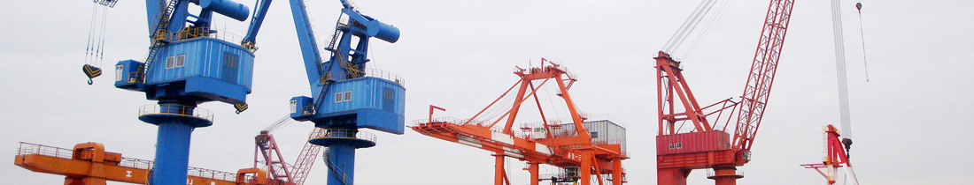

300T Goliath Gantry Crane
2018.06.01The 300T145m Goliath Gantry Crane is applied for hull constructions in shipyards (such as ship docks, slipways and etc.). The Goliath Gantry Crane has functions of hoisting up and down, swinging, turnover in the air by sections. The turnover by sections and closure operation are the special features. By means of the turnover operation by sections through two trolleys, the adjustment of hoisting up and down will be made first to have the Upper trolley bear the whole sections. The Lower trolley with no load will go through the underside of the Upper trolley and re-tie on the other side of the section. Finally the 180 degrees turnover operation can be completed by the Upper and Lower trolley's hoisting up and down, and the horizontal traversing movement of the Upper and Lówer trolleys.
The main girder of the Crane is of ladder-shaped monobox girder structure. Four rail tracks for the Upper and Lower trolleys traversing movement are arranged at upside and downside of the monobox girder. The maximum Twin-Lift capacity of the two trolleys is not more than 300T. During the turnover operation in the air, the section weight is not more than 300T. The rigid legs are connected with the main girder by the high-strength bolts. An elevator can be provided inside the rigid leg, and the operators can take the elevator to the inner side of the rigid leg from the bottom of rigid leg directly. The top of the main girder can be reached through ladder. Walkways will be provided on the main girder for the operator and maintenance persons access. The flexible legs are of triangle cannulation structures, and the two round pipes are equipped with ladders so that the operator can reach the top platform of the flexible leg or top of the girder directly. The flexible legs are connected with the main girder by the flexible hinges. The Gantry-long-travel mechanisms have totally 64pcs wheels, among which 2x16pcs are at the side of the rigid leg, and 2x16pcs are at the side of the flexible leg. The wheel bogies are connected with the supporting legs (the rigid leg and the flexible leg) through balance girders. The operator's cabin with good visual field is installed at the lower side of the upper trolley, and from the operator’s seat, the movement of the hooks within the operation range can be clearly observed.
A maintenance crane is equipped on the crane, which is located on the top of the main girder and at the side of the rigid leg. The maintenance crane’s lifting capacity, boom length and slewing angle will meet the maintaining requirement for the Upper and Lower trolleys.
The crane is powered through 3-Phase 6.6kV(±10%) 50Hz high-voltage, which is fed by the Power Cable reel. The Upper and Lower trolleys are powered by means of cable pulley moving cable device which is located on the main girder.
Main technical particulars
Lifting capacity
Total lifting capacity 300T
Upper trolley (I, II hooks) 2 x 150T
The biggest load difference between two hooks 100t
Lower trolley (III hook) 150t
Joint Twin-lift operation of Upper and Lower trolleys 300t
Turnover operation 300t
Component force of canting pull for main hooks (I, II, I)
Along Gantry-long-travel rail track direction 5% (abt. 3 degrees)
Along trolley-traversing rail track direction 10% (abt. 6 degrees)
Capacity of elevator Abt. 400kg
Main dimensions
Rail span 145m
Wheel Base gauge of leg 30m
Height of clearance (from bottom of girder to rail) 69.05m
Hoisting height
Above rail surface of main hooks (l, II) / below rail surface 70m/14m
Above rail surface of main hook (III) / below rail surface 62m/14m
Rail span of 2 x 150T Upper trolley 8m
Rail span of 150T / 30T trolley 6.5m
Hoisting speed
Upper trolley (I, II hooks) load 0 - 150t, 0.4 - 65m/min
no load, 0.4 - 13m/min
Lower trolley (III hook) load 0 - 150t, 0.4 - 65m/min
no load, 0.4 - 13m/min
Traversing speed of Upper and Lower trolleys
Wind velocity < 14m/sec 0.6 - 20m/min
Wind velocity < 8m/sec 0.6 - 30m/min
Gantry-long-travel speed
Wind velocity <14m/sec 0.6 - 20m/min
Wind velocity <8m/sec 0.6 - 30m/min
Elevator speed
400kg elevator speed 0.5m/sec
Maintenance crane
Lifting capacity 5T
Hoisting height Abt. 90m
Hoisting speed full load, 15m/min
No load, 30m/min
Trolley speed 20m/min
Slewing speed 0.5 r.p.m
, ;
Distance between lifting point and vertical center line of the rigid leg
Upper trolley (I, II hooks) 3.5m
Lower trolley (III main hook) 5.2m
Distance between lifting point and vertical center line of flexible leg
Upper trolley (I, II hooks) 3.5m
Lower trolley (III main hook) 5.2m
Minimum distance between Upper and Lower trolleys 11m
Wheel load
Maximum working wheel load of flexible leg Abt. 570kN
Maximum working wheel load of rigid leg Abt. 620kN
Maximum non-working wheel load of flexible leg 670kN
Maximum non-working wheel load of rigid leg 710kN
(The horizontal wheel load is calculated by 0.1 times of vertical wheel load.)
(The wheel load can be adjusted by adding or reducing the number of the wheels as per special requirement)
Wheel number
Rigid leg 2 x 16 = 32, driving ratio 1/2
Flexible leg 2 x 16 = 32, driving ratio 1/2
Diameter of wheel φ800mm
Type of rail track A120
Total installed power 2,000 KVA